out-of plane deformation measurements using cost-effective digital image correlation system
Accurate measurement of 3D full-field deformation is paramount for the development of modern applications in structural engineering. Over the past decade, digital image correlation, commonly referred to as DIC, has emerged as a promising optical-based displacement measurement technique. Its usage in experimental science has gained popularity due to its advantages, including ease of use, high spatial resolution, non-contact nature, and reusability.
While advanced DIC measurement systems exist, their high capital costs have limited their widespread adoption. Furthermore, most of the open-source DIC software systems are primarily designed for 2D measurements. Consequently, previous research efforts in DIC have predominantly focused on assessing materials with 2D deformations, with fewer studies addressing materials undergoing significant out-of-plane deformation.
This study introduces an innovative measuring tool based on DIC for the precise capture of 3D full-field out-of-plane deformation data. The proposed system utilizes commercially available digital cameras and employs MATLAB-based algorithms for data processing and analysis.
Uniaxial buckling tests were conducted on thin steel plate elements, considering their ability to induce significant out-of-plane deformations to validate the efficacy of this approach.


What is DIC ?
- Images are captured using stereo digital cameras
- Specimen surface features are tracked using correlation functions
- Deformation vector field is obtained
- Full field displacement / strain field is generated
Problems With The Existing Systems ?
- Commercially available DIC systems come with dedicated hardware that has high capital cost
- Studies have been carried out to create a low-cost alternative 3D DIC system
- Performance of these systems has not been tested for out-of-plane deformations
Aim of the Study
Create a cost-effective algorithm for accurate 3D full-field out-of-plane deformation measurements and verify its reliability for substantial deformations.
Components Of The Developed DIC System
1. Image Acquisition
The developed DIC algorithm has five main components. The first one is the image acquisition component. The images acquired in this stage can be categorized into calibration images and specimen images. the DIC algorithm determines the stereo camera’s parameters, such as focal length, radial distortion, and skew, using calibration images of the camera calibration pattern. Specimen images are needed for the DIC analysis

Experimental setup for image acquisition

Specimen covered with random speckle pattern

Imaging sensor – ELP 5-50mm lens, 8MP
1.1 Camera calibration involves determining both the intrinsic (internal geometrical and optical properties) and extrinsic parameters (positions and rotations in global coordinates) of a camera. This process utilizes predefined patterns, like checkerboards, to extract features such as corners and lines from captured images. The calibration plate is manipulated in various orientations within the volume of interest, and stereo cameras capture images for calibration. A minimum of 20 pairs of images is recommended for subpixel accuracy in DIC displacement measurements, leading to 40-50 images in a single calibration. The MATLAB built-in stereo camera calibrator program is employed to process the calibration, and the mean pixel error is estimated using the application.

Image acquisition for camera calibration

Calibration board orientations and a calibration plate

Position of the plate in 3D space
2. Image Rectification and Disparity Estimation
2.1 Image rectification is a process that aligns captured images vertically, simplifying the stereo-matching problem. By transforming images, the search for correspondences shifts from a 2D space to a 1D search along horizontal lines, reducing complexity and enhancing efficiency in the stereo-matching process.

Stereo images before rectification

Concept of image rectification
2.2 The disparity between two matching objects in a stereo image pair measures their horizontal separation, typically expressed in pixels. The disparity can be positive or negative, depending on conventions, and varies across the image. Disparity mapping techniques fall into two main categories: local methods and global methods. Local methods, such as Semi-Global Matching (SGM) and block matching (BM), analyze small image regions or patches to estimate disparities. On the other hand, global methods consider the entire image and use optimization techniques to determine disparities. In MATLAB, various functions are available to implement local and global disparity estimation methods, including SGM and BM algorithms. Employing both methods in the proposed system can lead to desirable results in terms of accurate disparity mapping and depth estimation.

Disparity map

Disparity estimation
3. 3D Scene Reconstruction
At each pixel point in the stereo images, the x, y, and z coordinates can be calculated based on the corresponding disparity values derived from the disparity map. These coordinates represent the spatial position of the pixel in the real 3D space. As a result, the 3D point cloud obtained through this reconstruction process can be represented as a three-dimensional array.


Reconstructed 3D point cloud

4. Feature detection and matching
Local features and their descriptors form fundamental components of numerous computer vision algorithms. These features represent patterns or distinct assemblies in an image, like points, edges, or corners. MATLAB’s computer vision toolbox offers various algorithms for detecting these local features and their descriptors. In a comparative analysis, the KAZE algorithm yielded the highest number of matched features. Consequently, the KAZE algorithm is integrated into determining the transformation matrix for defined subsets in considered image pairs.
Conventional Digital Image Correlation (DIC) compares a reference image with deformed images to estimate displacement fields. However, it struggles with large out-of-plane deformations, leading to invalid assumptions and a significant number of outlier-matched points. To address this, an incremental correlation method is developed in this study. This technique matches features between consecutive pairs of images, accumulating displacements in each step to capture progressive deformation. The final displacement field is derived by removing outliers in the cumulative matrix.

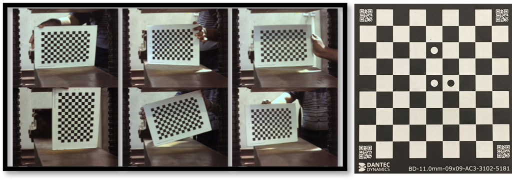
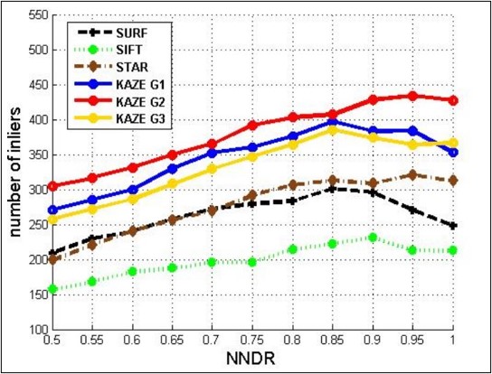
Comparison between the performance of different feature detection functions


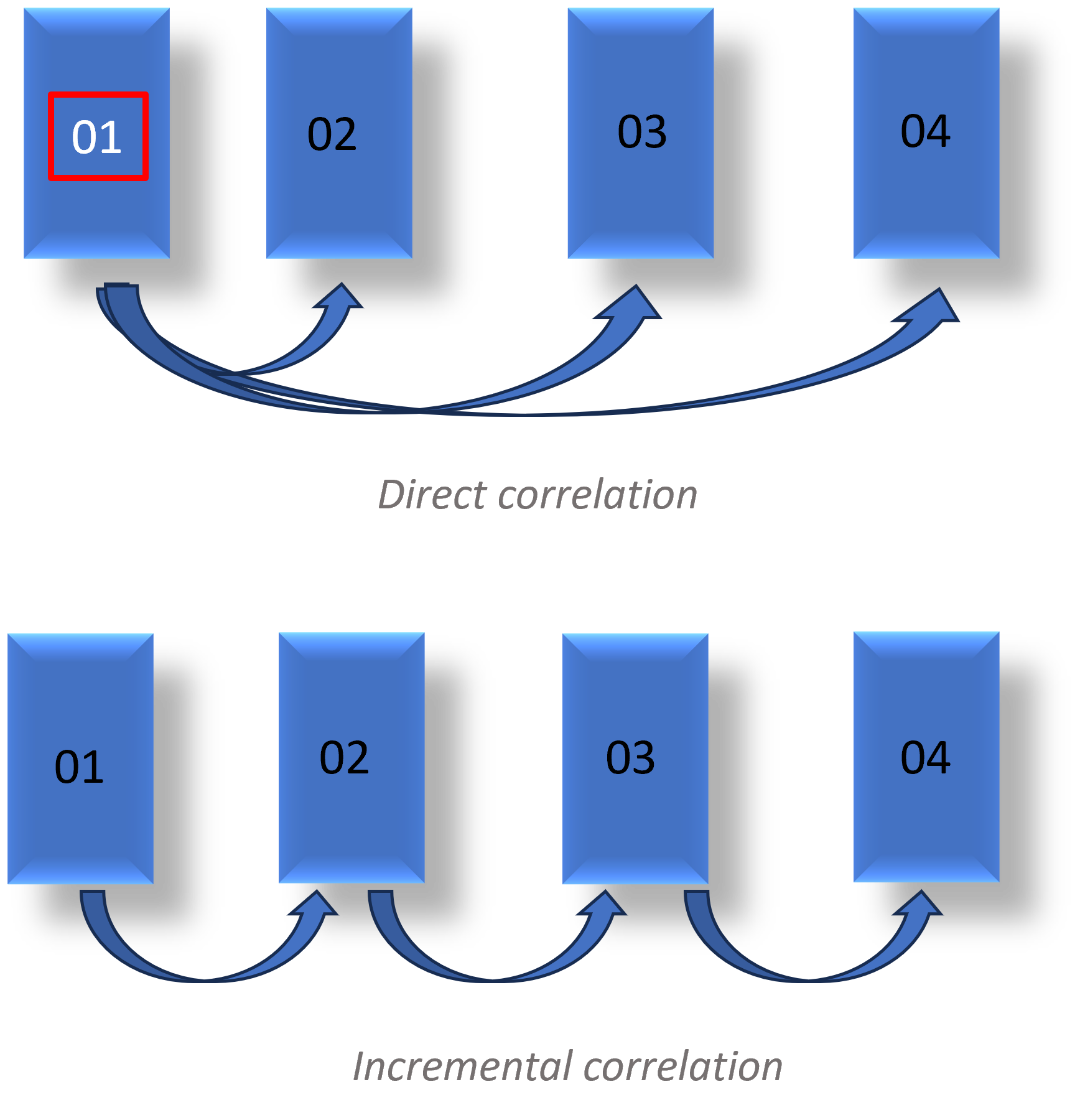
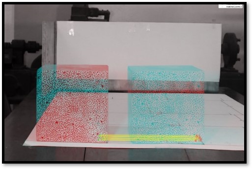
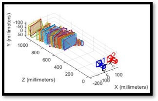
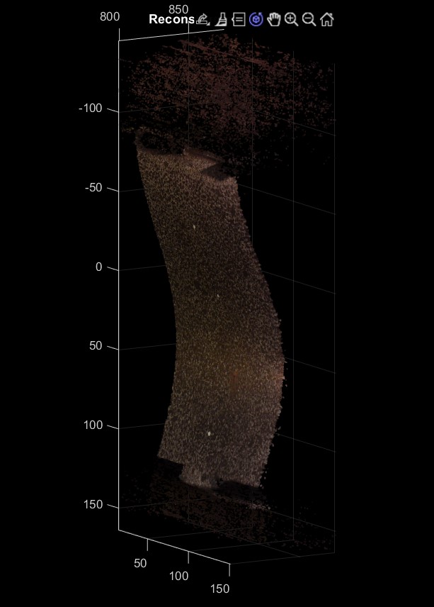
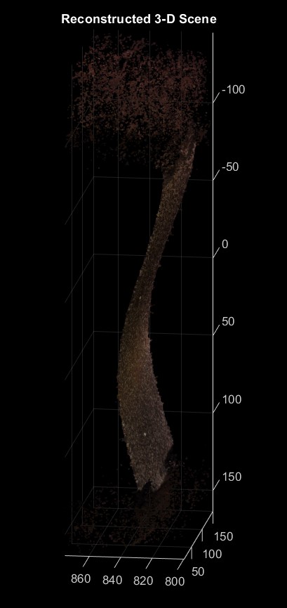
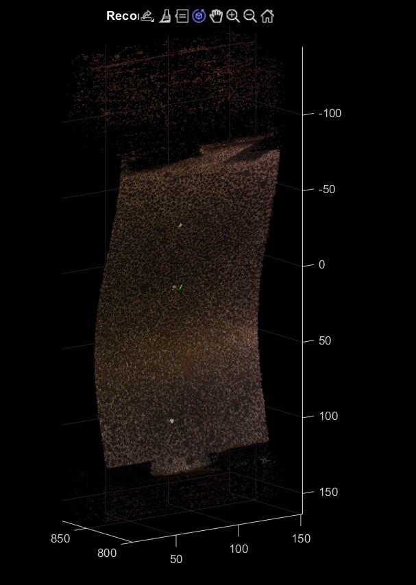
Feature matching between the deformed image and the reference image
5. Displacement calculation
The region of interest of the specimen image must be subdivided to ensure that each segment contains enough distinct local features for determining the transformation matrix post-deformation. In the undeformed image, the ROI is divided into several segments in terms of pixels, with shifts and overlaps in iterations to fully cover the selected ROI. The locations of these segments in the deformed image are tracked using the previously obtained transformation matrix.
From the initial coordinates and corresponding transformed coordinates of matched features, the following equations (1) and (2) are employed to calculate the displacement (δ) and strain (ε) values. Subsequently, the results can be visualized in both 2D and 3D spaces.

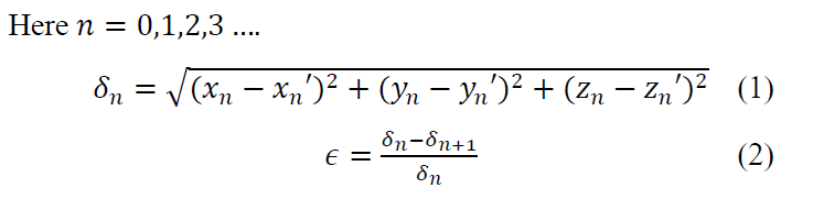
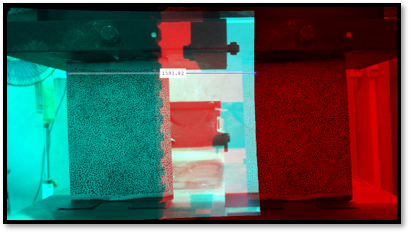
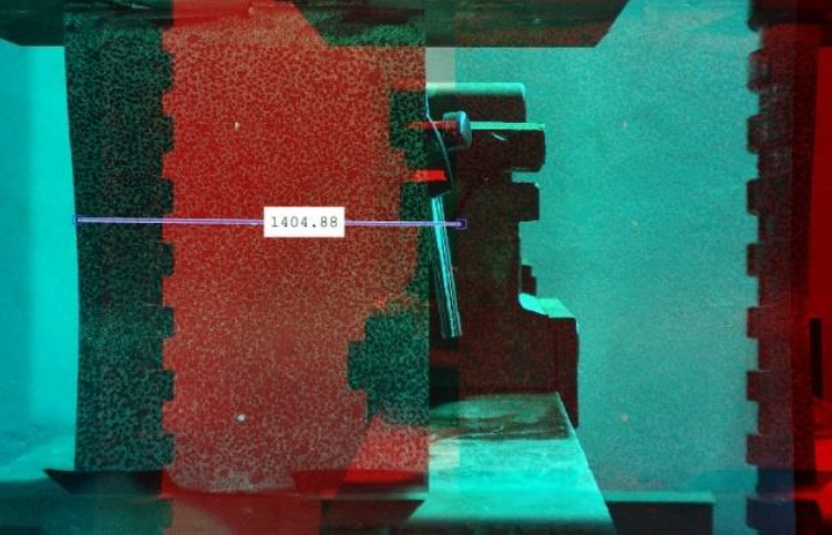
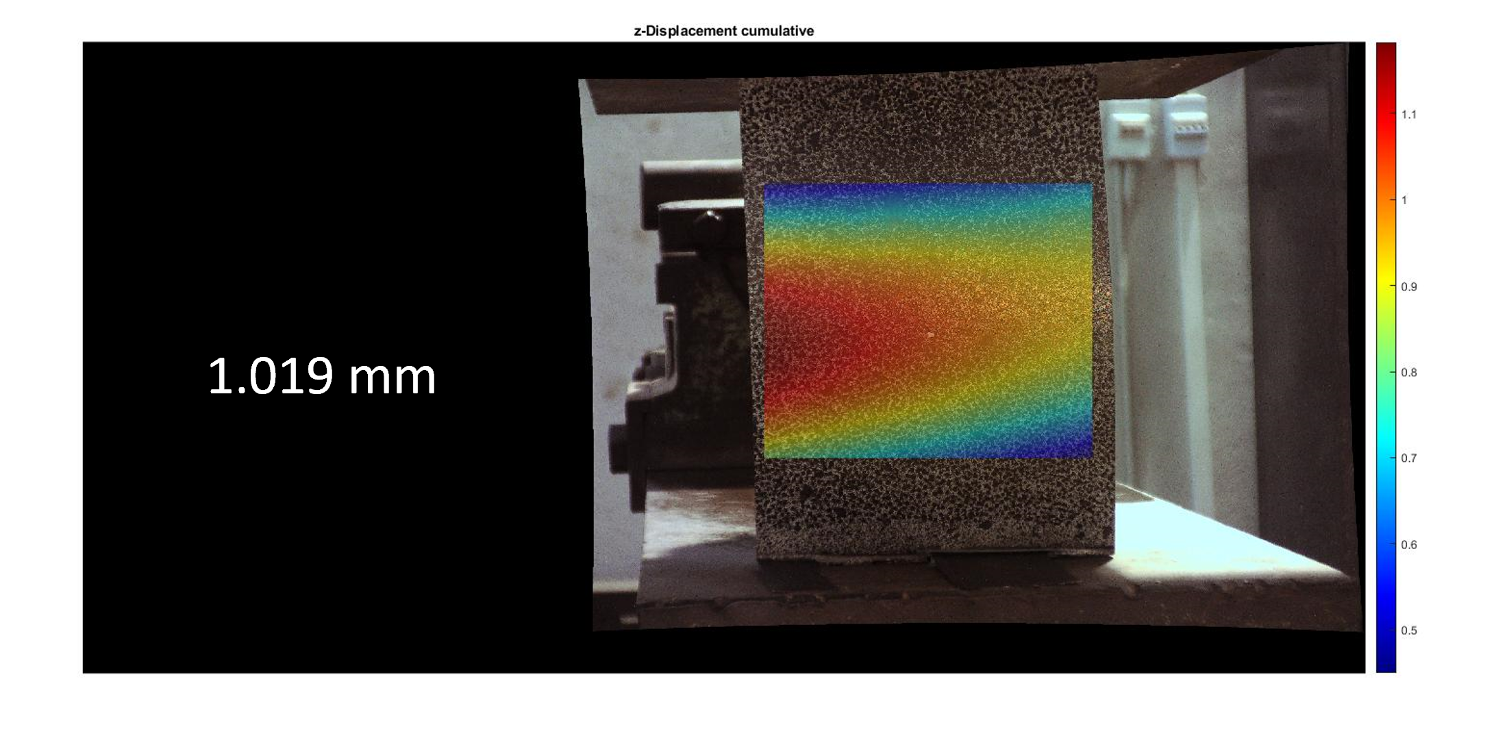
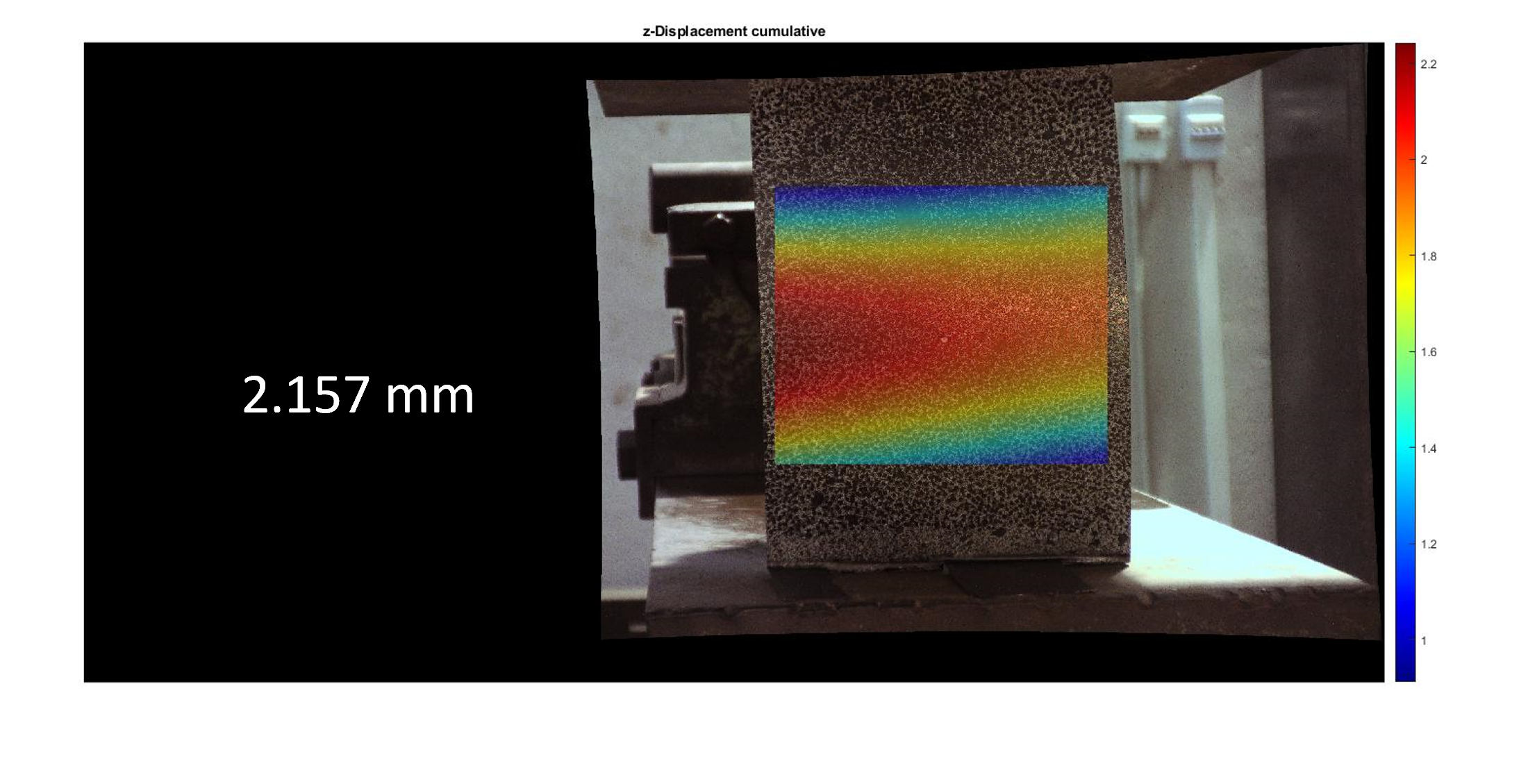
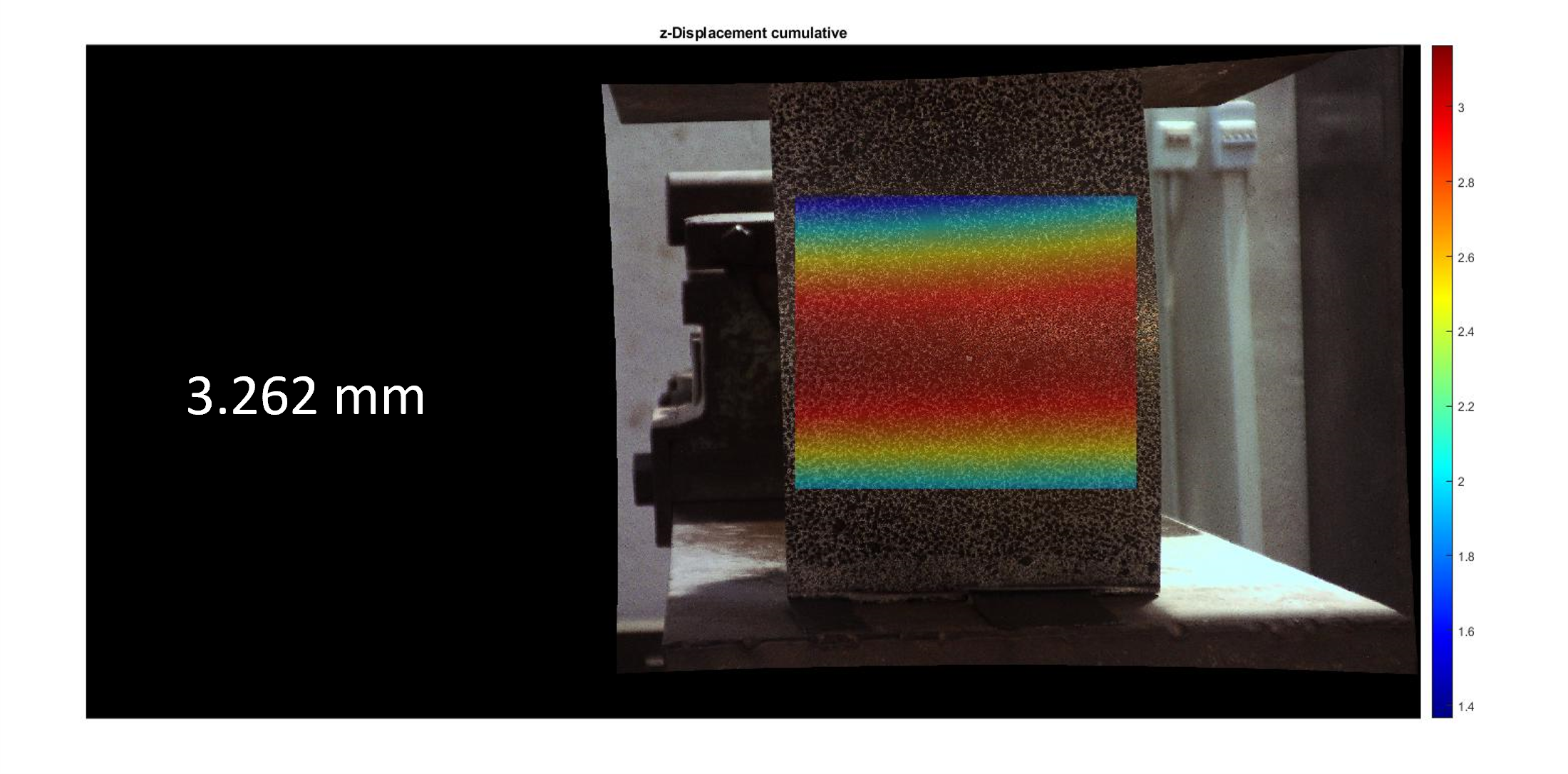
Calculation of displacement

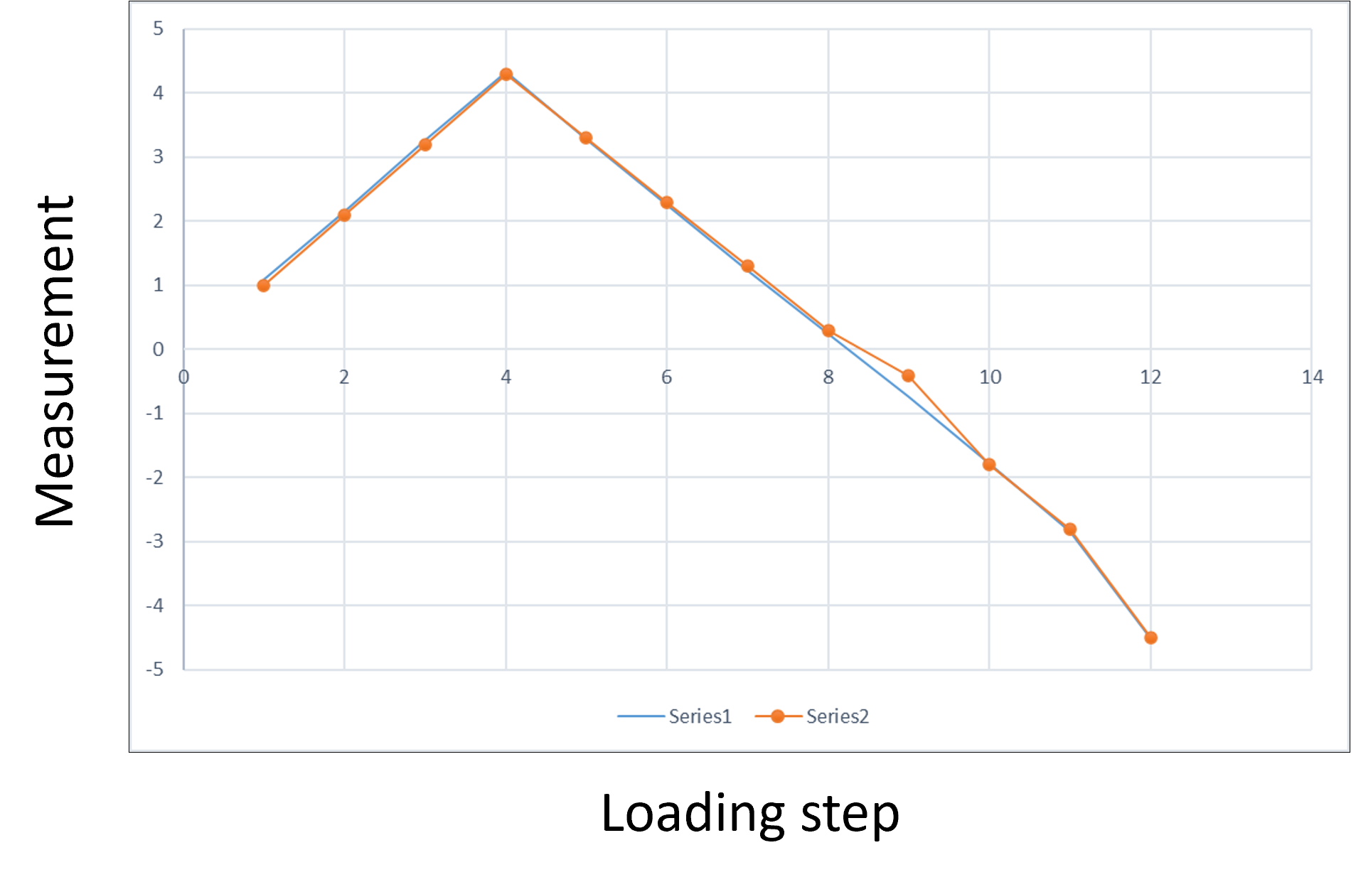
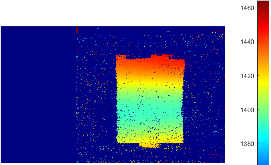
Results from DIC compared with dial-guage readings


Few contour plots obtained from the developed DIC system
The project was presented in the EXMO Engineering exhibition in 2023
